Home / Products
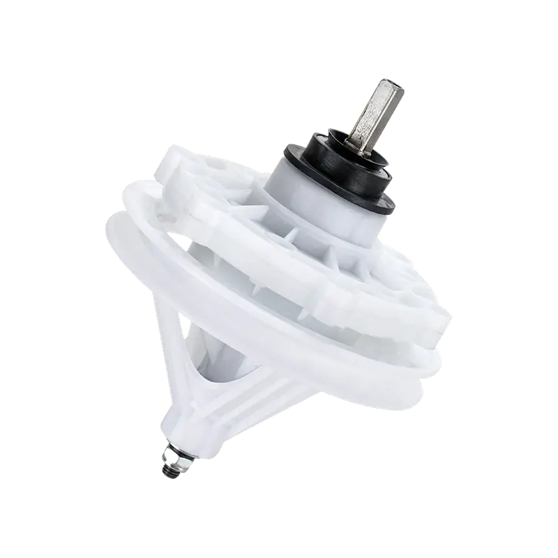
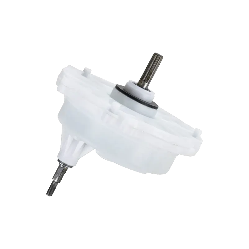
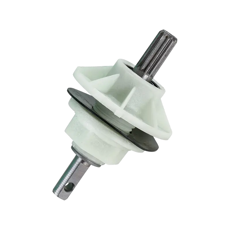
Washing Machine Components Wholesale
About Us
Cixi Gaite Electric Co., Ltd.
Founded in 2002, GAITE is a China Washing Machine Components Manufacturer and Custom Washing Machine Components Supplier based in Ningbo, Zhejiang. The company specializes in the R&D and manufacturing of core washing machine components, including gear reducers and synchronizers, providing reliable component solutions for OEM manufacturers and aftermarket applications.

With years of development, GAITE now operates a modern production base of approximately 10,000 m², supported by stable production capacity and mature manufacturing processes. Committed to quality, GAITE continuously optimizes product performance and structural design, providing customers with cost-effective component solutions.
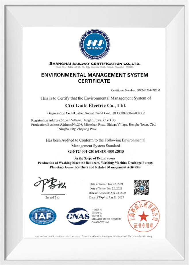
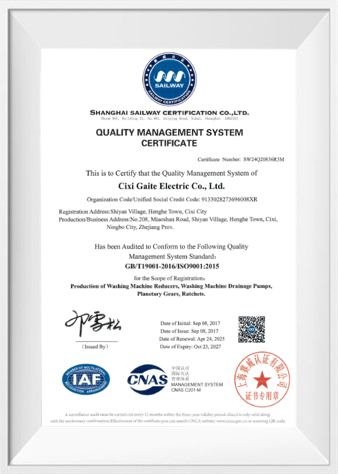
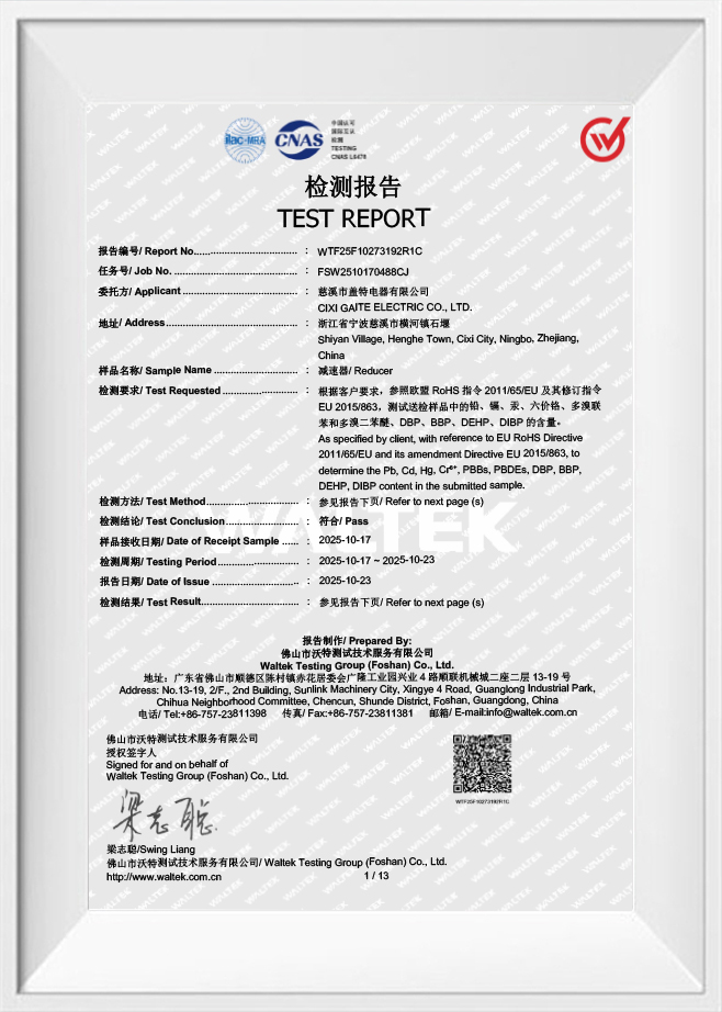
Certificate of Honor
News
Products Industry knowledge

1. Overview of Washing Machine Components

Washing machine components form the mechanical and electrical subsystems that convert motor power into the wash, rinse, and spin motions of a washing machine drum. This washing machine components category covers the gear reducers, synchronizers, and related drive-system parts that link the motor to the drum and control the timing of each cycle stage. Because these washing machine components operate together as a linked system, their individual design characteristics directly affect how a washing machine handles load, agitation speed, and cycle transitions.

A washing machine components manufacturer typically groups these parts into two functional layers: torque-transfer parts such as gear reducers and clutch assemblies, and cycle-control parts such as synchronizers and timer mechanisms. Buyers sourcing from a washing machine components supplier generally evaluate both layers together, since a mismatch between torque-transfer capacity and cycle-control timing can affect how consistently a washing machine completes its programmed sequence. The sections below describe the common component types found in this category, along with their working principles, application scenarios, and maintenance considerations.

2. Common Types of Washing Machine Components and Their Characteristics

(1) Gear Reducer and Gearbox Assemblies

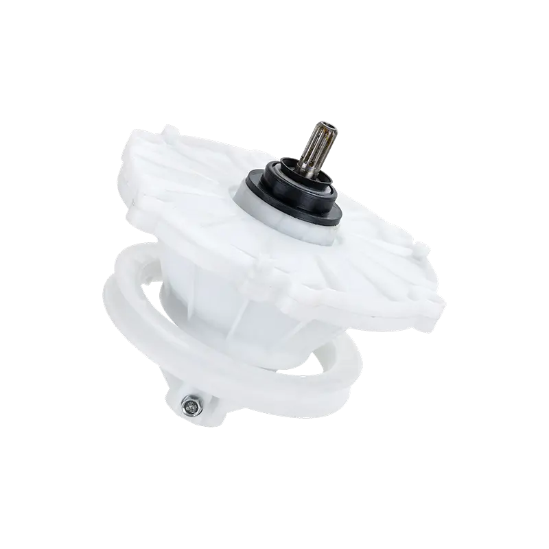
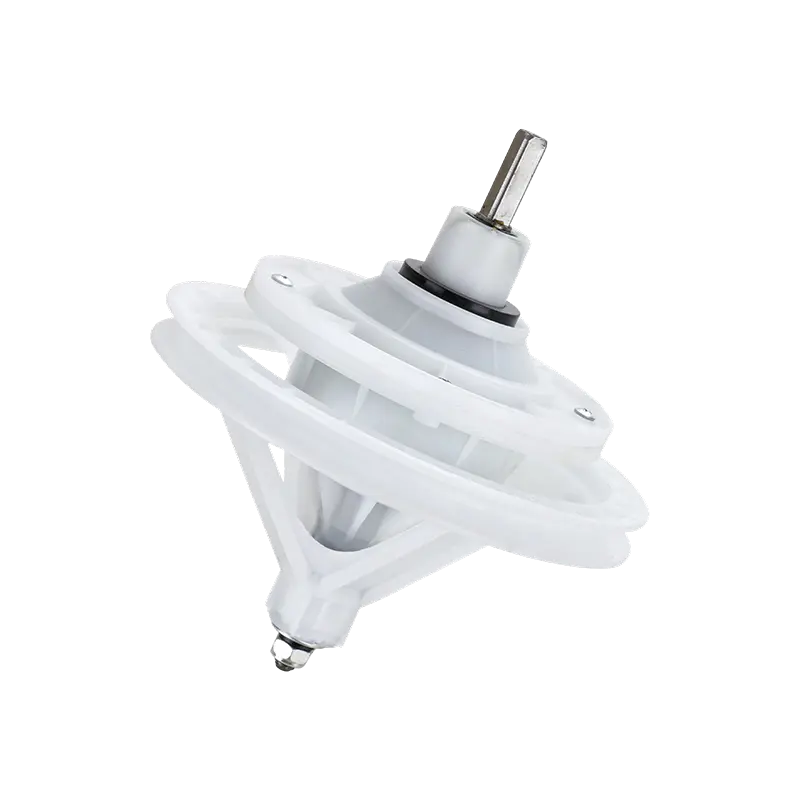
Gear reducers lower the rotational speed of the drive motor while increasing torque delivered to the washing machine drum shaft. Inside a typical gear reducer, a set of meshed gears steps down motor speed through a fixed ratio, allowing the drum to rotate slowly with high torque during wash agitation and to disengage or shift ratio during spin extraction. The housing is generally molded from engineering-grade plastic or a plastic-metal combination, chosen for dimensional stability under repeated torque reversal. Gear tooth profile and material selection influence how the assembly handles the load changes that occur each time the machine switches between agitation and spin. Within the washing machine components category, gear reducers are typically paired with a clutch or synchronizer mechanism that determines when torque is transferred to the drum shaft.

(2) Synchronizer and Timer Mechanisms

Synchronizers coordinate the sequence and duration of each washing machine cycle stage, switching electrical contacts to activate the motor, drain pump, and water inlet valve at the programmed points in the cycle. A mechanical synchronizer uses a motor-driven cam stack to open and close a series of electrical contacts in a fixed sequence, while an electronic synchronizer performs the same coordination through a control board and relay set. Contact material and cam profile accuracy determine how consistently the synchronizer switches between stages across repeated cycles. Because the synchronizer interacts directly with the gear reducer, motor, and pump, its timing accuracy affects how smoothly the washing machine transitions between wash, rinse, and spin phases.

(3) Related Components Commonly Sourced Together

Clutch assemblies, drum bearings, and drive belts are frequently sourced alongside gear reducers and synchronizers because they share mechanical interfaces within the same drive system. A clutch assembly engages or disengages the gear reducer output from the drum shaft, drum bearings support the rotating drum while resisting water exposure, and drive belts transfer motor rotation to the drum pulley in belt-driven designs. Buyers assembling a washing machine components order commonly request these parts together to reduce the number of separate interface checks required during final assembly.

Comparison of common washing machine component types and their maintenance characteristics
Component Type Primary Function Position in Drive System Primary Wear Factor Typical Maintenance Action
Gear Reducer / Gearbox Assembly Reduces motor speed and increases torque to the drum shaft Between motor output and clutch/drum shaft Gear tooth wear from repeated torque reversal Periodic lubrication and gear mesh inspection
Synchronizer / Timer Mechanism Coordinates timing of wash, rinse, and spin stages Connected to motor, pump, and valve circuits Contact wear from repeated switching cycles Contact inspection and cam profile check
Clutch Assembly Engages or disengages torque transfer to the drum Between gear reducer output and drum shaft Friction surface wear from engagement cycling Friction surface inspection and adjustment
Drum Bearing & Seal Supports drum rotation and resists water ingress Mounted at the rear or base of the drum housing Seal degradation from moisture exposure Seal condition check and lubrication renewal

Gear reducers and synchronizers differ across several functional dimensions, and comparing them side by side helps clarify why washing machine components suppliers treat the two parts as complementary rather than interchangeable. Torque handling, rotational speed control, mechanical complexity, electrical integration, application versatility, and maintenance frequency each vary between the two component types in a distinct pattern. Representing these six dimensions together on a single chart makes the trade-offs easier to see than listing them in separate paragraphs. The chart below uses a five-point scale for each dimension, where a larger value indicates a greater degree of that characteristic rather than a preferred outcome. Reading the two shapes together shows how a gear reducer and a synchronizer occupy different positions within the same washing machine components category despite working together in the same drive system.

Functional Comparison: Gear Reducer vs. Synchronizer Torque Handling Speed Control Mechanical Complexity Electrical Integration Application Versatility Maintenance Frequency Gear Reducer Synchronizer

The chart shows the gear reducer scoring highest on torque handling capacity and mechanical complexity, which reflects its role in physically transferring and reducing motor torque through a geared mechanism. Its electrical integration score sits at the lowest point on the chart because a gear reducer is a purely mechanical assembly with no internal switching function of its own. The synchronizer shows the opposite pattern, scoring highest on electrical integration level since its core function depends on switching electrical contacts rather than transferring mechanical load. Rotational speed control also favors the synchronizer, since it is the component that determines when the motor changes speed or direction rather than the component that physically carries that speed change. Maintenance frequency is moderate for both parts but tends to lean slightly higher for the gear reducer in applications with frequent heavy loads, since mechanical wear accumulates with torque cycling in a way that electrical contact wear does not always match. Application versatility sits closer to the middle for both components, reflecting that each part is typically adapted to a specific drum size and motor configuration rather than used identically across every washing machine model. Viewed together, the two shapes on the chart overlap only slightly, which illustrates why a washing machine components manufacturer generally designs and tests these two parts through separate engineering processes even when they are sold as part of the same drive-system package. This separation also explains why sourcing teams often request test data for the gear reducer and the synchronizer independently rather than accepting a single combined performance claim for both parts. Recognizing these differences early in the selection process helps a washing machine components supplier match the right combination of parts to a specific drum size, motor rating, and cycle program. The comparison also supports the maintenance guidance discussed later in this article, since a gear reducer and a synchronizer typically require different inspection routines based on the wear patterns shown here.

3. Application Scenarios and Selection Points

(1) Matching Components to Washing Machine Type

Front-load residential washing machines generally use a horizontal drum axis, which places a steady radial load on the gear reducer and drum bearing throughout the wash cycle. Top-load residential machines often rely on a vertical agitator or pulsator design, which changes the torque profile the gear reducer experiences during agitation compared with a horizontal-axis design. Commercial and institutional laundry equipment typically runs longer cycle programs with heavier average loads, which places additional demand on both the gear reducer and the synchronizer across a higher number of daily cycles. Selecting washing machine components that match the intended drum orientation and duty pattern reduces the likelihood of a mismatch between component rating and actual operating conditions.

Gear reducer components are not distributed evenly across every washing machine type, since drum orientation and duty pattern influence how frequently each machine category requires this type of component. Front-load, top-load, and commercial or institutional laundry equipment each place a different demand profile on the gear reducer, which affects how washing machine components suppliers plan production allocation across these three segments. The chart below presents an illustrative distribution showing the relative share of gear reducer component demand across these three washing machine categories. This distribution is intended to show general proportions rather than an exact market figure for any specific supplier or region. Viewing the three categories side by side on a single horizontal chart makes the relative scale easier to compare than reading the same figures in a paragraph.

Illustrative Application Distribution of Gear Reducer Components Front-Load Residential 45% Top-Load Residential 35% Commercial/Institutional 20%

Front-load residential washing machines account for the largest illustrative share in this chart, consistent with the horizontal-drum design's steady reliance on a gear reducer to manage torque throughout an extended wash and spin sequence. Top-load residential machines follow closely behind, reflecting the vertical-axis agitator design's own dependence on gear reduction to control agitator speed relative to motor speed. Commercial and institutional laundry equipment shows a smaller relative share in this particular distribution, though each individual unit in this category typically experiences a higher number of cycles per day than a residential machine, which changes the wear pattern even where the unit count is lower. These proportions can shift depending on regional appliance preferences, since some markets favor top-load designs more heavily than others. A washing machine components manufacturer that tracks demand across all three categories is generally better positioned to plan gear reducer production runs that match seasonal and regional ordering patterns. For a washing machine components supplier working with OEM programs across multiple machine types, this kind of distribution data also helps with production scheduling, since front-load and top-load orders often follow different seasonal patterns than commercial equipment orders. Selection points for procurement teams should account for which of these three categories a given order is intended to serve before finalizing gear ratio, housing material, and mounting dimension specifications. Commercial and institutional applications, despite a smaller unit share, often require a gear reducer rated for a higher duty cycle than the residential categories shown here. This distinction between unit volume and duty intensity is an important selection point that a simple share-of-demand chart cannot fully capture on its own. Buyers should therefore treat this chart as a starting reference point for planning purposes rather than the sole basis for a final component specification decision.

(2) Key Selection Criteria

  • Load capacity range relative to the rated drum capacity of the target washing machine model
  • Mounting dimension compatibility with the existing motor and drum shaft interface
  • Gear ratio matched to the required agitation and spin speed profile
  • Electrical contact rating appropriate for the synchronizer's expected switching frequency
  • Housing and seal material suited to the expected moisture and temperature exposure

Reviewing these criteria together, rather than evaluating gear ratio or contact rating in isolation, helps a procurement team avoid selecting a washing machine component that fits one specification but conflicts with another during final assembly. Component solutions produced by Cixi Gaite Electric Co., Ltd., a Ningbo, Zhejiang-based washing machine components manufacturer established in 2002, are generally evaluated against these same selection points before being supplied to OEM production lines or aftermarket distribution channels. The company operates a production base of approximately 10,000 square meters focused on gear reducer and synchronizer manufacturing, supplying both OEM manufacturers and aftermarket customers as part of its ongoing component development work.

4. Working Principles and Application Behavior

(1) Gear Reduction and Torque Transfer Principle

A gear reducer lowers rotational speed and increases torque according to the ratio between its input and output gear sets. As the motor turns the input gear at its rated speed, the meshed output gear rotates more slowly while transferring a proportionally higher torque to the drum shaft. This relationship allows a relatively small, high-speed motor to drive a much larger drum load without requiring a physically larger motor. During the spin phase, many gear reducer designs shift or disengage this ratio through a clutch mechanism, allowing the drum to reach higher rotational speeds once the heavier torque demand of the wash phase has ended.

(2) Synchronization and Cycle Timing Principle

A synchronizer manages the transition between wash, rinse, and spin stages by switching a defined sequence of electrical contacts as its internal cam or control logic advances. Each contact closure activates a specific circuit, such as the water inlet valve during fill, the motor circuit during wash and spin, or the drain pump circuit between stages. The rotational speed profile of the drum through a typical cycle illustrates how these two components work together across a full wash-spin sequence.

Drum rotational speed does not remain constant through a washing machine cycle, since each stage places a different mechanical demand on the gear reducer and a different timing instruction from the synchronizer. During fill and wash phases, drum speed typically stays low to support gentle mechanical action against the load. As the cycle advances toward spin extraction, the synchronizer signals the gear reducer and clutch assembly to shift into a higher-speed configuration. The chart below traces an illustrative rotational speed profile across six representative phases of a standard wash-spin cycle. Reading this profile alongside the earlier discussion of gear reduction and synchronization principles shows how the two components coordinate their behavior at each stage transition.

Illustrative Drum Rotational Speed Profile (RPM) 0 400 800 1200 Fill Wash Rinse Spin Ramp-Up Peak Spin Spin Down

The chart begins with a near-zero rotational speed during the fill phase, when the drum typically remains still or turns only briefly to distribute water and detergent. Speed rises slightly during the wash phase as the gear reducer drives the drum through a slow agitation pattern suited to mechanical cleaning action rather than extraction. The rinse phase shows a similar low-speed pattern, since rinse cycles generally repeat the same gentle agitation used during the wash phase rather than introducing additional mechanical stress. A sharp increase appears at the spin ramp-up phase, which marks the point where the synchronizer signals the clutch and gear reducer to shift into the higher-speed configuration used for water extraction. Peak spin speed represents the highest point on the chart, corresponding to the stage where the gear reducer output is least engaged and the drum rotates closer to direct motor speed for maximum extraction force. The spin-down phase shows a controlled decrease back toward a lower speed, allowing the drum to slow gradually rather than stopping abruptly, which reduces mechanical shock on the gear reducer and drum bearing. This overall profile demonstrates why the gear reducer and synchronizer must be matched to each other rather than selected independently, since a mismatch between gear ratio and switching timing can cause the drum to reach peak speed later or earlier than the programmed cycle intends. A washing machine components supplier that tests gear reducer and synchronizer pairs together, rather than testing each part in isolation, is more likely to identify this kind of timing mismatch before the parts reach production. For OEM buyers, this cycle profile is also useful as a reference point when specifying gear ratio and switching timing for a new washing machine model, since the intended peak spin speed and ramp duration directly influence both component specifications. Recognizing how drum speed changes across the cycle also supports the maintenance guidance in the next section, since the spin ramp-up and peak spin phases place the highest mechanical stress on the gear reducer and are therefore the points most closely associated with long-term wear.

5. Application Cases and Maintenance Guidance

(1) Typical Application Cases

In residential front-load washing machines, gear reducer assemblies typically pair with a variable-speed motor and an electronic synchronizer to manage a wide range of program options, from delicate low-speed cycles to higher-speed spin extraction. In residential top-load machines with a vertical agitator, the gear reducer more often works with a mechanical synchronizer that switches between agitation and spin through a simpler cam-based sequence. Commercial and institutional laundry equipment generally uses a heavier-duty gear reducer paired with a synchronizer or control system rated for a higher number of daily cycles, since this equipment typically runs continuously across extended operating hours rather than intermittently.

(2) Maintenance Guidance

Routine maintenance for gear reducer assemblies generally includes periodic inspection for unusual noise during operation, visual checks of the gear housing for cracking or excessive play, and renewal of internal lubrication at intervals suited to the unit's duty cycle. Synchronizer maintenance typically focuses on inspecting electrical contacts for pitting or excessive wear and confirming that cam-driven switching remains consistent across repeated cycles. Drum bearing and seal maintenance should include a check for water seepage around the seal area, since moisture intrusion is a common early indicator of seal wear that can eventually affect bearing performance. Following a consistent inspection interval for these components helps identify wear patterns before they progress to a stage that affects overall washing machine performance.

6. Frequently Asked Questions

(1) What is the function of a gear reducer in a washing machine drive system?

A gear reducer lowers the rotational speed of the drive motor while increasing the torque delivered to the drum shaft, allowing a comparatively small motor to move a larger drum load during the wash and spin stages.

(2) How does a synchronizer coordinate the stages of a wash cycle?

A synchronizer switches a defined sequence of electrical contacts, using either a motor-driven cam stack or an electronic control circuit, to activate the water valve, motor, and drain pump at the correct point in the programmed cycle.

(3) What should be considered when selecting washing machine components for a specific model?

Selection should account for load capacity range, mounting dimension compatibility, gear ratio, electrical contact rating, and housing material suited to the expected moisture and temperature conditions of the target washing machine.

(4) How often should gear reducers and synchronizers be inspected for maintenance purposes?

Inspection intervals generally depend on duty cycle, with heavier-use equipment such as commercial laundry machines requiring more frequent checks for gear wear, contact condition, and seal integrity than typical residential use.

(5) Can washing machine components be customized for OEM production requirements?

Gear reducer and synchronizer specifications, including gear ratio, mounting dimensions, and switching sequence, can generally be adapted to match a specific washing machine model as part of an OEM component development process. A washing machine components manufacturer such as Cixi Gaite Electric Co., Ltd. develops this type of custom component solution for OEM manufacturers and aftermarket customers.