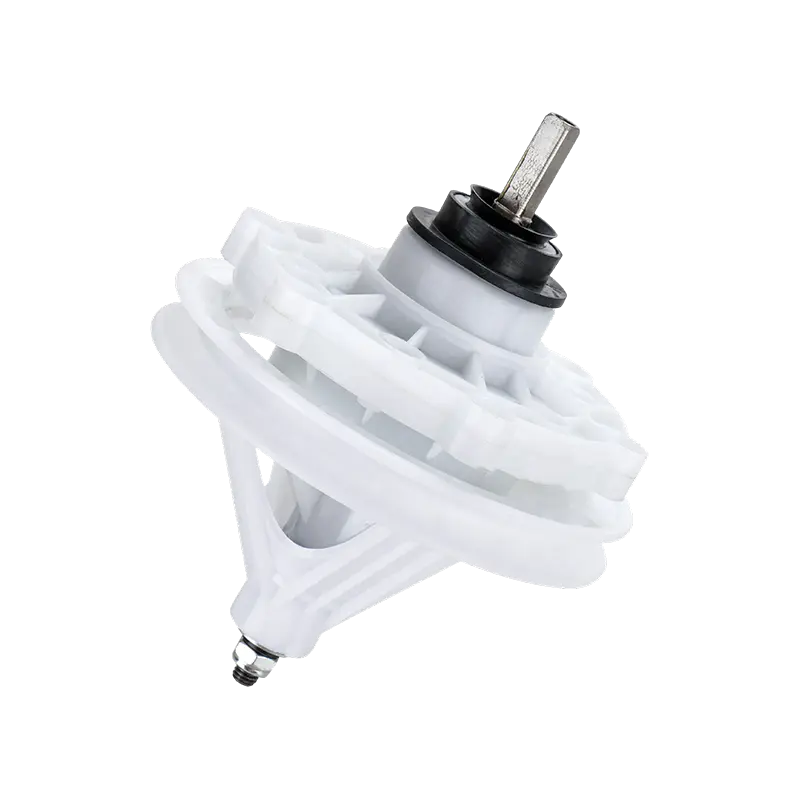
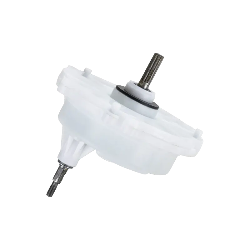
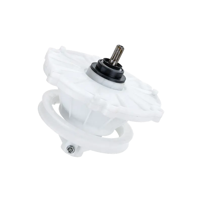
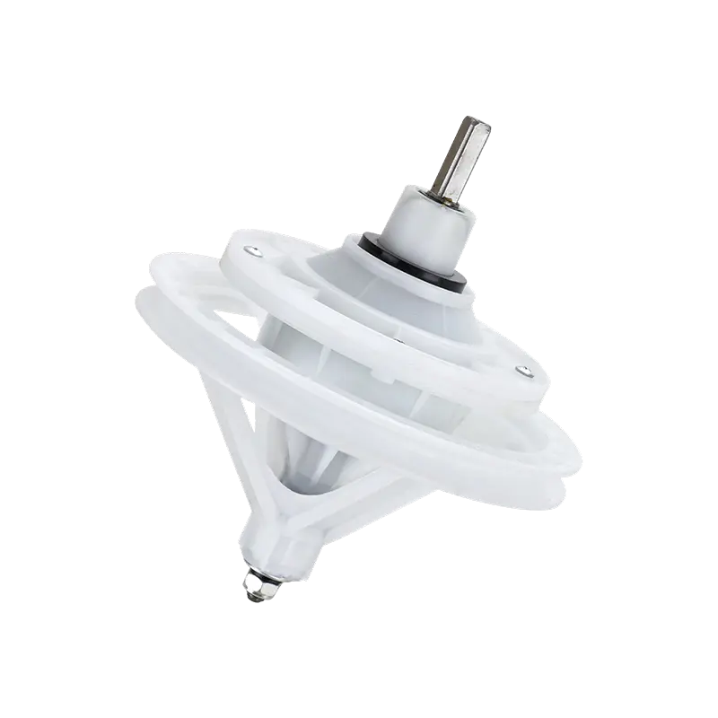
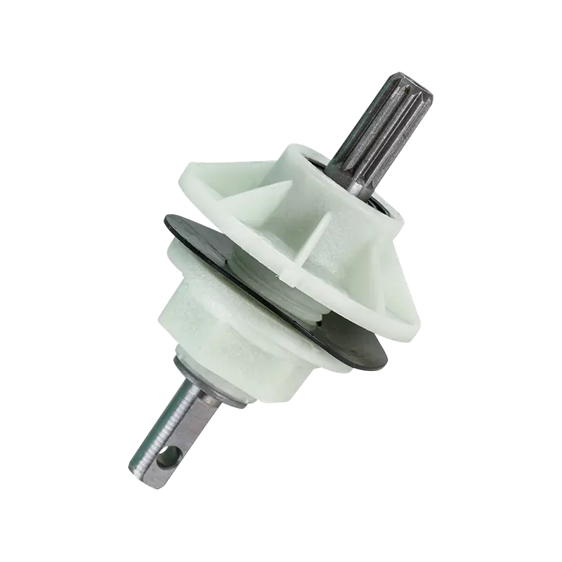
A washing machine P-shaft manufacturer supplies the pulsator shaft that connects a washer's gearbox output directly to the pulsator or agitator disc, transmitting rotational torque while withstanding constant water exposure and repeated load reversal during the wash cycle. Selecting the right P-shaft manufacturer and pulsator shaft assembly supplier depends primarily on spline configuration, shaft material, and sealing compatibility rather than on price alone, since these factors determine how well the shaft resists wear, leakage, and premature play over years of operation. The sections below cover the common P-shaft types available, how they are structurally built, where each configuration fits best, how the main options compare, and how to keep a pulsator shaft assembly performing reliably over its service life.
Common Types of Washing Machine P-Shafts and Pulsator Shaft Assemblies
A washing machine P-shaft manufacturer typically produces several shaft configurations, distinguished mainly by how the shaft engages with the pulsator or agitator disc and how it is supported within the tub assembly. Recognizing these categories helps buyers specify a shaft that matches both the mechanical interface and the load profile of the target washer platform.
Splined P-Shafts
Splined P-shafts use a series of parallel ridges machined along the shaft's engagement section, mating with a corresponding internal spline in the pulsator hub. This configuration distributes torque across multiple contact surfaces rather than a single key, which reduces localized stress and allows the shaft to transmit higher torque loads without loosening over repeated direction reversals during the agitation cycle.
Keyed P-Shafts
Keyed shafts rely on a single rectangular key seated in a matching keyway on both the shaft and the pulsator hub to transmit torque. This design is mechanically simpler and generally more cost-efficient to manufacture than a splined interface, though it concentrates load on a narrower contact area, which can make it more prone to developing play over an extended service life under heavy or frequent reversal cycles.
Tapered P-Shafts
Tapered shafts use a conical engagement surface that draws tight against the pulsator hub as a retaining nut is torqued down, creating a self-centering, friction-based connection in addition to any keying feature. This configuration tends to resist loosening effectively over time, since the taper geometry maintains contact pressure even as minor wear develops at the interface.
Stepped Shafts
Stepped P-shafts incorporate multiple shaft diameters along their length, with a larger-diameter section supporting the bearing and seal interface and a smaller-diameter section forming the pulsator engagement point. This layered geometry allows the shaft to be optimized separately for bearing load capacity and for pulsator torque transfer rather than compromising both functions on a single uniform diameter.
Integrated Shaft-Bearing Assemblies
Some pulsator shaft assemblies are supplied as a pre-assembled unit combining the shaft, bearing, and seal into a single serviceable module. This approach simplifies installation for OEM assembly lines and aftermarket repair alike, since the critical alignment between shaft, bearing, and seal is established during manufacturing rather than during field assembly.
Splined
Distributes torque across multiple contact surfaces for high reversal loads.
Keyed
Simple, cost-efficient single-key torque transfer interface.
Tapered
Self-centering friction fit that resists loosening over time.
Stepped
Multiple diameters optimize bearing support and torque transfer separately.
Integrated Shaft-Bearing
Pre-assembled shaft, bearing, and seal module for simplified installation.
Load capacity is one of the clearest differentiators among these P-shaft configurations, and comparing them side by side helps narrow a sourcing shortlist before detailed drawings are exchanged. The column chart below presents an approximate relative torque-handling capacity for each shaft type, based on general mechanical component principles rather than a specific manufacturer's certified rating. These figures are meant for directional comparison only, since actual capacity depends heavily on shaft material, diameter, and manufacturing precision. Reviewing this alongside the expected pulsator load of a target washer platform is a practical first step in shaft-type selection. It also explains why certain shaft types appear more frequently in higher-capacity washer platforms than in compact or entry-level models.
The column chart shows stepped and tapered P-shafts sitting at the higher end of the relative torque capacity index, reflecting how their design allows engineers to optimize the engagement geometry independently from the bearing support section rather than compromising both on a single uniform shaft diameter. Splined shafts follow closely behind, benefiting from their multi-surface load distribution across the spline teeth, which spreads torque more evenly than a single-key interface can achieve. Keyed shafts sit at the lower end of the comparison, consistent with their simpler, more cost-efficient design that concentrates torque transfer on a narrower contact area rather than distributing it across multiple surfaces. This pattern generally lines up with how these shaft types are distributed across washer capacity tiers, with keyed shafts appearing more often in compact or lighter-duty platforms and splined or tapered shafts appearing more often in mid-to-large capacity machines subject to more frequent or forceful reversal cycles. For an OEM engineering team, this comparison is useful as an early filter when a new platform's expected pulsator torque profile is already known, since it narrows the realistic shaft-type shortlist before physical prototyping begins. Aftermarket buyers can apply similar reasoning when trying to identify a likely shaft configuration for an unfamiliar washer model based on its stated capacity rating. It is also worth noting that shaft material and heat treatment interact with shaft-type geometry to determine actual torque capacity, so two shafts of the same type from different manufacturers will not necessarily perform identically under sustained load.
Key takeaway: Stepped and tapered P-shaft configurations generally offer the highest relative torque capacity, making them the categories most worth evaluating for mid-to-large capacity washer platforms with frequent reversal cycles.
Working Principles and Structural Design of Pulsator Shaft Assemblies
A pulsator shaft assembly transmits rotational torque from the gearbox output through the tub wall to the pulsator disc, while simultaneously providing structural support and maintaining a water-tight seal across the tub boundary. This dual mechanical and sealing function is what distinguishes P-shaft design from a simple drive shaft used elsewhere in the machine.
Torque Transmission Interface
At the pulsator end, the shaft engages the pulsator hub through its splined, keyed, or tapered interface, transmitting the oscillating torque generated by the gearbox output. This interface must resist not only sustained torque but also the repeated direction reversal inherent in the agitation cycle, which places cyclic stress on the engagement surfaces far more demanding than steady one-direction rotation would produce.
Bearing Support
A bearing, typically housed within the tub's center post or within the gearbox housing itself, supports the shaft radially and axially as it passes through the tub wall. Bearing selection needs to account for both the radial load from the pulsator's mass and any axial thrust introduced during spin-mode operation on machines where the same shaft assembly participates in basket rotation.
Sealing Function
A rotary shaft seal, typically a lip seal or a combination of a mechanical seal with a secondary water slinger, prevents wash water from migrating along the shaft into the gearbox or bearing cavity. Seal performance depends heavily on shaft surface finish at the seal contact point, since even minor surface irregularities can accelerate seal lip wear and allow gradual water intrusion over time.
Material and Surface Treatment
P-shafts are commonly manufactured from stainless steel, coated carbon steel, or in some designs an engineered composite material, each offering a different balance of corrosion resistance, torque capacity, and manufacturing cost. Surface treatments such as hard chrome plating or nitriding are frequently applied at the seal contact zone specifically to reduce wear at that critical interface, even when the remainder of the shaft is manufactured from a less corrosion-resistant base material.
Manufacturing precision plays a substantial role in how well these structural elements function together. Shaft straightness and concentricity directly affect how evenly load is distributed across the bearing and seal contact surfaces, and even small deviations can introduce vibration that accelerates wear at both the torque-transmission interface and the sealing zone. Consistent control of these tolerances across a production run is one of the more reliable indicators of a P-shaft manufacturer's overall process maturity.
Key takeaway: Because a P-shaft must transmit torque and maintain a water-tight seal simultaneously, shaft straightness, surface finish at the seal zone, and bearing alignment are the manufacturing factors that most directly determine long-term reliability.
Application Scenarios and Selection Criteria for OEM and Aftermarket Buyers
Selecting the right P-shaft or pulsator shaft assembly depends on how the buyer intends to use it, whether specifying a new OEM platform or sourcing a compatible replacement for existing installed washers.
OEM Selection Priorities
Shaft diameter and spline count matched to gearbox output specification
Seal compatibility validated against the tub material and expected water exposure
Documented runout and concentricity tolerance for design validation
A pulsator shaft assembly supplier capable of custom engineering for a proprietary chassis
Aftermarket Selection Priorities
Cross-model compatibility across multiple washer generations
Availability of the shaft as an individual part rather than a full tub assembly only
A washing machine P-shaft supplier with consistent lead times for repair scheduling
Clear labeling of shaft length, diameter, and spline pattern to reduce ordering errors
Machine capacity is one of the most important sizing variables. Larger-drum washers designed for heavier wet loads place greater bending and torsional stress on the P-shaft during agitation, so a shaft specified for a compact machine should not be substituted into a higher-capacity chassis even where the spline pattern happens to be compatible. Regional water chemistry also matters, since hard water conditions can accelerate mineral deposit formation around the seal contact zone, which in turn increases friction and wear at that interface over time.
Buyers should also consider how the P-shaft integrates with the rest of the drive system. A shaft that is dimensionally compatible with the gearbox output but poorly matched in material hardness to the mating spline can wear unevenly, transferring stress concentration to whichever component is softer. This is why many OEM programs prefer sourcing the P-shaft and gearbox from a manufacturer with engineering familiarity across the broader transmission system rather than treating the shaft as an isolated commodity part.
The relationship between shaft diameter and load capacity is a useful reference point during early sizing decisions. The scatter chart below plots a representative relationship between shaft diameter and approximate maximum torque capacity across a range of P-shaft samples, based on general mechanical design principles for cylindrical torque-transmitting shafts rather than a specific test dataset. This kind of visualization helps illustrate that the relationship is not perfectly linear, since larger shafts also benefit from a proportionally larger section modulus. Reviewing this alongside a target washer's torque requirement helps engineers avoid both over-specifying an unnecessarily large shaft and under-specifying one that risks premature fatigue failure.
The scatter chart shows a clear upward relationship between shaft diameter and approximate torque capacity, but the spacing between points widens as diameter increases, which reflects the disproportionate gain in section strength that comes from even modest diameter increases in a cylindrical shaft. Data points clustering around the smaller 14 to 18 millimeter diameter range sit toward the lower end of the torque capacity axis, consistent with their common use in compact or lighter-duty washer platforms. Points in the 22 to 26 millimeter range occupy the middle of the chart, representing the diameter band most frequently specified for mainstream mid-capacity residential washers. The widest torque capacity values appear at the 26 to 30 millimeter range, aligning with larger-capacity or heavier-duty platforms designed to handle bigger wet loads and correspondingly higher reversal torque during agitation. The gap between successive diameter groupings also grows wider moving up the chart, illustrating that a shaft's resistance to torsional stress increases faster than its diameter increases in linear terms, a relationship well established in general mechanical engineering principles for cylindrical shaft design. For sourcing teams, this pattern is a useful sanity check when reviewing a supplier's proposed shaft diameter for a given torque specification, since a diameter that falls well outside the expected cluster for its stated torque rating may warrant a closer look at the underlying material and heat treatment assumptions. It also helps explain why increasing shaft diameter by even a small margin is often a more efficient way to add safety margin than switching to a fundamentally different shaft material at the same diameter. Buyers evaluating a P-shaft supplier's technical documentation can use this general relationship as a reasonable plausibility check against the specific figures a manufacturer provides for their product line.
Key takeaway: Torque capacity increases faster than shaft diameter in linear terms, meaning modest diameter increases can provide meaningful safety margin without requiring a change in shaft material.
Detailed Comparison of Washing Machine P-Shaft Configurations
The table below summarizes how the primary P-shaft configurations compare across the criteria most relevant to sourcing decisions.
General comparison of washing machine P-shaft and pulsator shaft assembly configurations.
Criteria
Splined
Keyed
Tapered
Torque Distribution
Even, multi-surface
Concentrated, single key
Friction-based, self-centering
Resistance to Loosening
Moderate
Lower over time
Higher
Manufacturing Complexity
Higher
Lower
Moderate
Typical Application
Mid-large capacity washers
Compact, entry-level washers
Long-service platforms
Material selection is another important comparison dimension, since the shaft's base material affects corrosion resistance, weight, and manufacturing cost simultaneously. The donut chart below illustrates an approximate distribution of P-shaft material usage across current washer production, based on general appliance component industry observation rather than any single brand's proprietary sourcing figures. This distribution is meant to give a directional sense of how common each material choice is, helping buyers gauge whether their own specification aligns with prevailing industry practice.
Approximate P-shaft material distribution across current household washer production.
Material
Approximate Share
Stainless Steel
46%
Coated Carbon Steel
34%
Engineered Composite
20%
The donut chart shows stainless steel holding the largest share of P-shaft material specification, which is consistent with its strong inherent corrosion resistance in an application that is constantly exposed to water and detergent chemistry. Coated carbon steel follows as the second most common choice, offering a lower base material cost while relying on a protective coating, such as hard chrome plating or a specialized polymer coating, to achieve adequate corrosion resistance at the shaft surface. Engineered composite materials hold the smallest but still meaningful share, reflecting growing interest in weight reduction and inherent corrosion immunity for shaft body sections that do not require the same wear resistance as the seal and spline contact zones. The relatively even three-way split shown here indicates that no single material has become a universal default, and material selection continues to depend on a manufacturer's specific cost, weight, and durability priorities for a given platform. For buyers evaluating a P-shaft supplier, understanding which material a proposed shaft uses helps set realistic expectations for corrosion performance in their specific regional water conditions. It is also worth noting that coating quality matters as much as base material choice for coated carbon steel shafts, since a coating that wears through prematurely can expose the underlying steel to accelerated corrosion at a rate that may undermine the cost advantage the coated approach was intended to provide. Composite shaft options, while less common, are worth evaluating specifically for platforms where overall assembly weight reduction is a stated design priority rather than a secondary consideration.
Key takeaway: Stainless steel remains the most widely specified P-shaft material for its inherent corrosion resistance, though coated carbon steel and engineered composites each remain relevant for platforms prioritizing cost or weight reduction respectively.
Maintenance Guidance for Washing Machine P-Shafts and Pulsator Shaft Assemblies
Because a P-shaft operates at the intersection of mechanical load transfer and water sealing, maintenance attention typically focuses on both function areas rather than one in isolation.
Check for excessive play or wobble at the pulsator hub, since developing looseness at the shaft engagement point is often the earliest detectable sign of spline, key, or taper wear.
Inspect around the shaft seal area for water staining or mineral deposit buildup, which can indicate early-stage seal wear before a more significant leak develops.
Listen for a knocking or clunking sound during direction reversal in the agitation cycle, which frequently points to accumulated play at the shaft-to-pulsator interface.
Verify that the pulsator retaining nut or fastener remains properly torqued, particularly on tapered shaft designs where fastener tension directly maintains the friction fit.
Avoid habitually overloading the drum beyond its rated capacity, since sustained overload increases both torsional stress on the shaft and axial load on the supporting bearing.
When replacing a shaft, confirm diameter, spline pattern, and overall length match the original specification precisely, since even small dimensional mismatches can introduce misalignment that shortens the life of the new component.
For repair technicians, sourcing from a pulsator shaft assembly supplier that documents shaft runout and concentricity tolerances for their product line can help confirm that a replacement shaft meets an appropriate precision standard, particularly for higher-capacity platforms where alignment sensitivity is greater.
Runout, the amount a rotating shaft deviates from a true straight axis as it turns, is one of the more useful precision indicators for evaluating shaft quality during incoming inspection or after a suspected impact event. The gauge below illustrates a general benchmark runout tolerance that well-manufactured P-shafts are typically expected to meet, expressed as a percentage of an acceptable maximum threshold used in general precision shaft manufacturing practice. A shaft measuring well within this benchmark is generally considered suitable for installation, while one approaching or exceeding the threshold may introduce vibration and accelerated wear once installed.
The gauge shows a typical benchmark of around 88% of the maximum allowable runout threshold for a well-manufactured P-shaft under standard incoming inspection, meaning the shaft's measured deviation sits comfortably within an accepted precision range rather than approaching the rejection limit. Maintaining consistency near this benchmark across a full production run depends heavily on controlled turning and grinding processes, since even a well-designed shaft can exceed acceptable runout if machining tolerances drift during manufacturing. A shaft that measures significantly above this benchmark, even if still technically within a maximum allowable limit, is more likely to introduce audible vibration once installed and may wear its bearing and seal interfaces more quickly than a shaft measuring well within the benchmark. For OEM quality teams, tracking incoming runout measurements across supplier batches can serve as an early indicator of manufacturing process drift before it becomes a field reliability issue. For repair technicians performing bench inspection on a shaft suspected of impact damage, a runout measurement noticeably outside the expected benchmark range is a reasonable basis for recommending replacement rather than continued use. It is worth noting that acceptable runout thresholds can vary somewhat depending on shaft diameter and length, so this benchmark should be treated as a general reference point for typical P-shaft dimensions rather than a fixed universal standard applicable to every configuration.
Key takeaway: Monitoring shaft runout during incoming inspection provides an early, measurable indicator of manufacturing precision that correlates directly with long-term bearing and seal life.
Industry Trends in Washing Machine P-Shaft Manufacturing
Several developments are shaping how P-shafts and pulsator shaft assemblies are engineered and sourced across the appliance manufacturing industry, and staying aware of them helps buyers plan sourcing strategy rather than reacting to availability alone.
As consumer expectations around washer capacity and duty cycle intensity continue to rise in many regional markets, demand has grown for shaft configurations that distribute torque more evenly, contributing to the continued relevance of splined and stepped shaft designs alongside traditional keyed configurations. Corrosion resistance has also become a more prominent evaluation criterion, with buyers increasingly asking suppliers for documented material composition and coating specifications rather than accepting a general material category alone, particularly for platforms sold into hard-water or high-humidity regional markets.
Pre-assembled integrated shaft-bearing modules have also gained traction as OEM assembly lines look to reduce installation variability, since establishing shaft-to-bearing alignment during manufacturing removes a source of potential error that would otherwise occur during final assembly. Alongside this, more sourcing programs are requesting structured runout and durability testing data as part of supplier qualification, reflecting a broader industry shift toward evaluating manufacturing consistency through documented process control rather than relying solely on a component's stated specification sheet.
Founded in 2002, Cixi Gaite Electric Co., Ltd. is a China washing machine transmission parts manufacturer, custom washing machine P-shaft manufacturer, and pulsator shaft assembly supplier based in Ningbo, Zhejiang. The company focuses on the research, development, and manufacturing of core washing machine transmission components, including gear reducers, synchronizers, and related shaft assemblies, supplying both OEM production programs and aftermarket repair channels. Operating a production base of approximately 10,000 square meters supported by stable production capacity and established manufacturing processes, the company continues to refine shaft precision and structural design with the aim of delivering cost-effective component solutions across its product range.
Key takeaway: Growing emphasis on documented corrosion resistance, pre-assembled shaft-bearing modules, and supplier testing transparency are the trends most likely to shape P-shaft sourcing decisions going forward.
Frequently Asked Questions About Washing Machine P-Shafts
What does a washing machine P-shaft manufacturer typically supply?
A washing machine P-shaft manufacturer typically supplies splined, keyed, tapered, and stepped pulsator shafts, along with pre-assembled shaft-bearing-seal modules, for both OEM production lines and aftermarket repair channels.
How do I know which P-shaft configuration fits my washer platform?
Matching the correct P-shaft configuration depends primarily on the pulsator hub's engagement pattern, the platform's expected torque and reversal frequency, and shaft diameter, all of which should be verified against a pulsator shaft assembly supplier's technical specifications before final selection.
What causes play or wobble at the pulsator over time?
Developing play at the pulsator typically results from gradual wear at the spline, key, or taper engagement surfaces, or from a loosened retaining fastener, and is usually one of the earliest detectable signs of shaft or hub wear during routine inspection.
Can a custom washing machine P-shaft supplier engineer a shaft for a proprietary chassis?
Manufacturers with in-house research and development capability can generally engineer a P-shaft to match a proprietary diameter, spline pattern, and length specification, provided the buyer supplies detailed dimensional and load requirement documentation during sourcing.
Why does shaft material matter for a pulsator shaft assembly?
Shaft material affects corrosion resistance in a component constantly exposed to water and detergent chemistry, as well as overall weight and manufacturing cost, which is why stainless steel, coated carbon steel, and engineered composites each remain relevant choices depending on a platform's specific priorities.
Is a pre-assembled shaft-bearing module better than sourcing components separately?
A pre-assembled shaft-bearing-seal module can reduce installation variability by establishing alignment during manufacturing rather than field assembly, though sourcing components separately may still suit programs with an established, well-controlled in-house assembly process.

 English
 عربى


 +86-574-63256717 /63267914
info@gaite.cn
 gaite@gaite.cn
 No. 208 Miaoshan Road, Shiyan Village, Henghe Town, Cixi City, Ningbo City, Zhejiang Province, China
