A washing machine parts diagram is the fastest way to explain how a washer works and the slowest way to order the right component. A technician opens the service manual, finds the exploded view, follows the numbers, and still ends up holding a gearbox with the correct housing and the wrong output spline. The drawing did its job perfectly. The problem is that a washing machine parts diagram shows position, not specification.
This guide is written for people who work with these drawings every week: repair shops, aftermarket distributors, procurement staff at appliance assembly plants, and engineers who have to approve a replacement part before it reaches a production line. It covers what a parts diagram actually contains, which areas are drawn in the least detail, how to convert a label into a measurable part, and where the real risk sits in a purchase order.
We build these components. Cixi Gaite Electric Co., Ltd., based in Cixi, Ningbo, Zhejiang, has been manufacturing washing machine gearboxes, gear reducers, synchronizers, P-shafts, clutch assemblies and drive shafts since 2002, supplying both OEM production lines and aftermarket channels. That background shapes the advice below, because most of the expensive mistakes we see begin with a diagram being read too literally.
A washing machine parts diagram answers where a component goes. It never answers whether the component in your hand will fit, and treating it as a shopping list is the single most common source of wrong orders.
What a Washing Machine Parts Diagram Really Shows
There are three drawings hiding under the same name, and mixing them up wastes time. The exploded assembly view separates parts along an axis so you can see how they stack. The sectional or cutaway view slices the machine in half so you can see what happens inside a housing. The wiring schematic shows electrical paths only and says nothing about mechanics. When a buyer says the diagram is confusing, nine times out of ten they are holding a schematic and looking for a gear.
An exploded drawing is organized by assembly hierarchy, not by function. Service documentation for a top-load machine commonly splits the product into a top frame assembly, an inner tub assembly, an outer tub assembly, a total assembly and a packing assembly. That structure is useful for a factory, because each group is built and stocked separately. It is awkward for a repair shop, because one physical failure can touch three groups at once. A leaking tub seal, for example, belongs to the outer tub assembly in the drawing, but the part that caused the leak may sit in the inner tub assembly, and the water damage appears in the drive assembly.
Labels also follow the deck layout of the machine. Along the top frame you will typically find the lid handle, the washing powder box, the softener inlet, the fog-washing or overflow device, the filtering bag and the control panel. Those names are descriptive, not standardized. Two manufacturers can use three different names for the same lid hinge, and neither of them is wrong.
Index numbers add another layer of confusion. In most manuals, numbering restarts inside every assembly, and a revision changes the index number without changing the drawing. So the same part number can appear under two different index numbers in two editions of the same manual. If you are building a cross-reference table for an aftermarket catalogue, always work from the part number column, never from the index bubble.
Read the drawing for structure and the parts list for identity, then confirm fit with measurements, because index numbers are the least reliable piece of information on the page.
The Assembly Groups Behind Almost Every Diagram
Once you recognize the groups, most manuals from different brands start to look similar. The names change, the layout does not.
- Top frame and control group. Lid, hinges, detergent and softener dispensers, filter bag, control panel, timer or electronic board, and the knobs or membrane switches that sit on it.
- Inner tub or drum group. The rotating basket, the pulsator on a top-load machine, the balance ring, the spider or hub that connects the basket to the shaft, and the shaft itself in some designs.
- Outer tub group. The stationary tub, bearing housing, tub seal, suspension rods or shock absorbers, and the hoses that connect it to the pump.
- Drive group. Motor, pulley, belt or direct coupling, gearbox or reducer, clutch assembly, brake, synchronizer, and the drive shaft that carries torque to the basket or pulsator.
- Plumbing and drainage group. Inlet valve, supply hose, drain pump, drain hose, lint filter and the drain selector that decides where water goes.
- Cabinet and packing group. Panels, feet, sound insulation, carton, foam blocks and the accessories bag.
Every failure conversation eventually lands in the drive group, because that is the only group where a small dimensional error turns into a large functional problem. A door seal that is two millimetres off leaks a little. A gearbox with the wrong ratio or the wrong output spline either refuses to assemble or destroys itself in a few dozen cycles.
Six assembly groups cover almost every washer diagram, and the drive group is where a diagram alone is never enough to place an order with confidence.
Reading the Drive Section Without Guessing
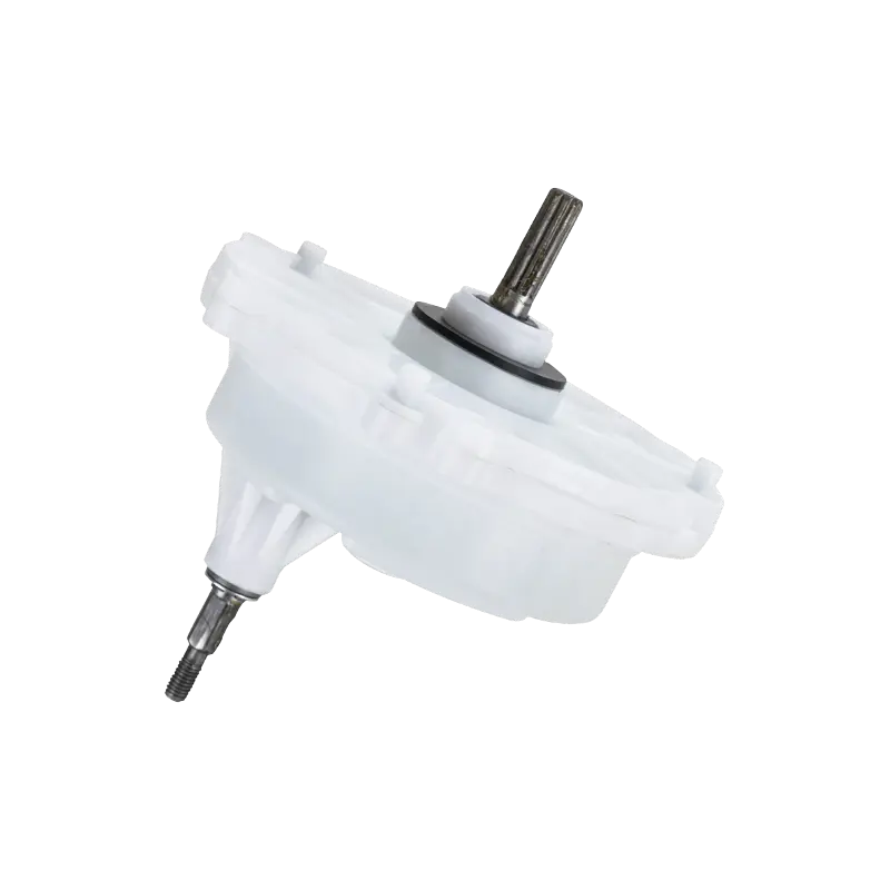
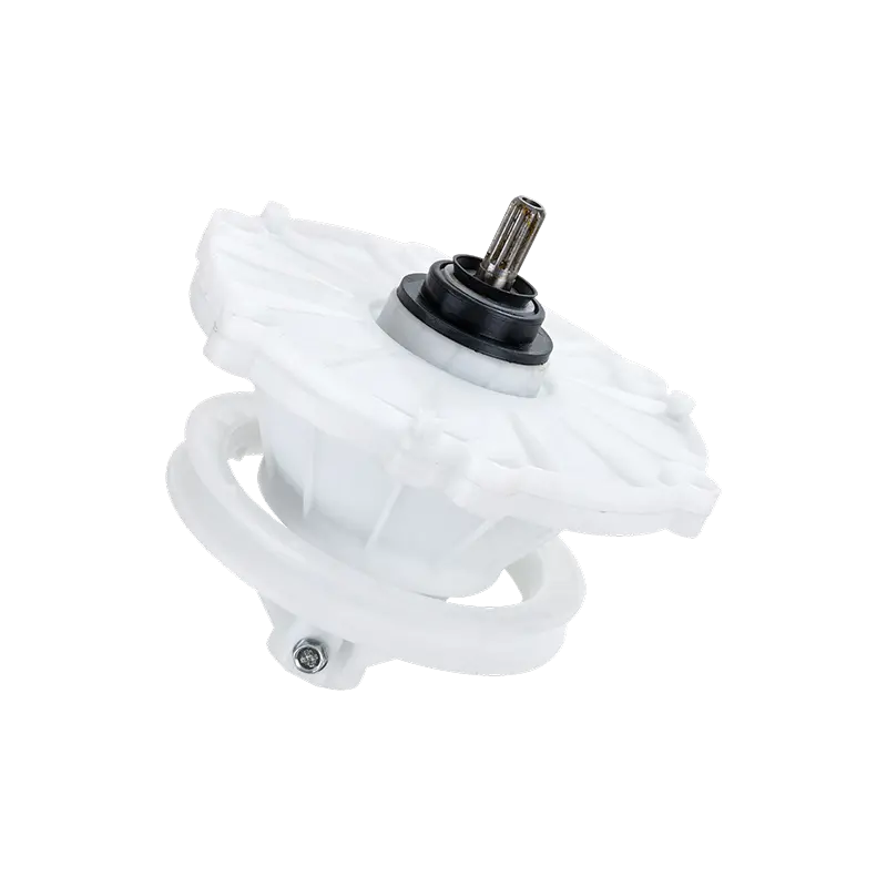
The drive section is where most drawings stop being helpful. On a top-load machine, the exploded view usually shows a motor, a belt, a large housing, and an output shaft that disappears behind the tub. Everything inside that housing is left to the parts list: the number of gear stages, the reduction ratio, the brake mechanism and the synchronizing actuator. That is workable for a factory technician who already knows the platform, and difficult for everyone else.
The chain of motion is worth memorizing because it tells you what to measure. The motor turns. A belt or a direct coupling passes that rotation to a gearbox or reducer. The gearbox converts one fast rotation into two useful behaviours: a slow oscillation for washing, and a single direction at higher speed for spinning. A clutch or brake assembly decides which of those two the drum receives, and a synchronizer coordinates the timing so the brake releases only after the drain path is open and the water level has dropped.
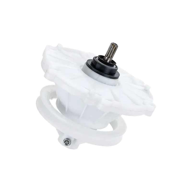 Washing Machine Gearbox ManufacturerTwin-tub Washing Machine ReducerView Product →
That sequence explains why so many replacement gearboxes are returned. If the housing bolts line up and the shaft diameter matches, the part installs. It only fails later, when the machine either cannot build up spin speed or the brake will not hold. Both symptoms point to internal differences that no drawing shows.
Belt-Driven, Direct-Drive and High-Torque Designs
A belt-driven gearbox lives with side load. Belt tension pulls the input shaft sideways, so bearing selection and housing stiffness matter more than they do on a direct-drive unit. A direct-drive gearbox sees higher torque at lower speed and usually runs with tighter concentricity requirements between the motor and the gear train. High-torque transmission units sit at the heavy end: larger tubs, higher wet loads, and a greater need for consistent backlash and lubrication.
For a buyer, the practical difference appears in the measurement checklist. Direct-drive units are usually specified by mounting pattern, spline geometry and ratio. Belt-driven units add pulley diameter, belt groove profile and input shaft keyway. High-torque units add bearing class and lubrication specification. Ask which of these the supplier can document before you compare prices.
What to Measure Before You Order
- Output shaft diameter and overall length, measured with a calliper rather than a ruler.
- Spline count, spline major diameter and the presence or absence of a keyway.
- Mounting bolt pattern, including hole spacing and thread size.
- Rotational direction of the output under normal drive, confirmed on the machine, not on the drawing.
- Gear ratio, or the number of input turns needed for one output turn.
- Brake band width and drum diameter if the clutch is integrated into the housing.
- Seal bore size and the condition of the shaft surface where the seal runs.
Measurements beat drawings every time: a gearbox that fits mechanically can still fail functionally if the ratio, brake or rotation direction does not match the original platform.
P-Shaft and Pulsator Shaft: The Small Part That Stops a Machine Cold
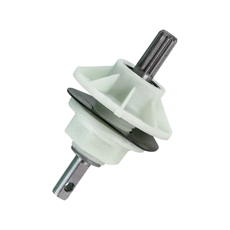
The P-shaft, also called the pulsator shaft, carries torque from the gearbox output up through the tub and into the pulsator. It is a short part in a drawing and a critical part in practice, because it passes through the tub seal and therefore sits in the wettest, most contaminated area of the machine. Detergent residue, lint and hard water all attack the same few surfaces.
A diagram will show you the shaft, the seal and the pulsator as separate bubbles. It will not show you hardening depth on the spline, coating thickness on the seal journal, straightness, or the surface finish that determines how long a lip seal survives. Those are the details that decide whether the shaft lasts five years or five months, and they are exactly the details a low-cost supplier removes first.
When a machine loses agitation but still drains and spins, or when water appears under the tub after agitation, the P-shaft assembly is one of the first places to inspect. Typical evidence includes a rounded spline, a polished or grooved seal journal, and rust staining where the shaft enters the tub. Once the seal journal is grooved, replacing only the seal rarely holds, because the new lip cannot seat against a worn surface.
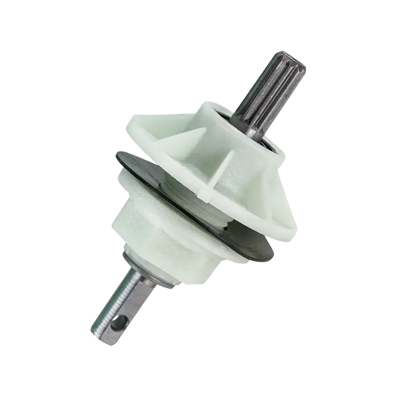 Washing Machine P-Shaft ManufacturerSemi-Automatic Twin-Tub Washing Machine GearboxView Product →
Good practice for repair shops is to treat the shaft and seal as one service item. For distributors building a catalogue, the useful specification set is short: shaft diameter, spline profile, total length, thread size at the top, and the material and heat treatment used on the spline. A washing machine parts manufacturer that controls its own heat treatment can usually document those points, while a trading company reselling mixed stock often cannot.
Shaft and seal belong together: replacing a worn P-shaft without renewing the tub seal, or the reverse, is one of the most predictable repeat-failure patterns in washer repair.
Twin-Tub and Semi-Automatic Washers Follow a Different Diagram
Twin-tub and semi-automatic machines are built on a simpler architecture, and their diagrams look different in ways that matter. There are two tubs instead of one, two timers or a combined timer, a manual or motorised drain selector, and a wash gearbox that produces the oscillating motion while a separate spin system handles extraction. The clutch assembly and synchronizer that dominate an automatic washer drawing may be absent, combined differently, or replaced by a simple spring-loaded brake.
The wash gearbox on a twin-tub machine is usually belt driven and lives with continuous reversing load. Its wear pattern is different from an automatic gearbox, which spends most of its life in one direction during spin. Reversing stress tends to show up at the worm or gear mesh, at the bearing seats, and at the output shaft where the pulsator couples. That is why a twin-tub gearbox that still turns by hand can already be noisy under load.
 Twin-tub Washing Machine ReducerThe Twin-tub Washing Machine Reducer is the core power device of semi-automatic twin-cylinder washing machines, responsible for converting the high-speed rotation of t...View Product →
For buyers serving markets where twin-tub machines still hold a large share, the practical specification list includes tub capacity, belt groove type, pulley diameter, output shaft length and the footprint of the mounting flange. It is worth noting that semi-automatic gear boxes appear under several names in catalogues, including gear case and transmission, and the naming difference does not always indicate a design difference.
Why the Reducer Drawings Are Often Incomplete
Semi-automatic reducers are frequently drawn as an outline with a single output shaft, because the internals are considered a supplier responsibility. That places more weight on the supplier's own drawings and first-article reports. If you are sourcing replacement reducers for a repair market, ask for a dimensioned drawing, not just a photograph. A photograph cannot tell you the backlash, the gear ratio, or whether the housing is machined from cast iron or stamped from sheet steel.
On twin-tub and semi-automatic machines the diagram is only a starting point, so the reducer's ratio, pulley geometry and mounting flange must come from the supplier's own documentation.
Synchronizers, Clutch Assemblies and Drive Shafts
These three parts are grouped together because they all handle switching, and switching parts are the ones most often misdiagnosed on a parts diagram.
A synchronizer in a washing machine is the mechanism that changes the drive path so one motor can serve two very different jobs. During washing, the drive oscillates and the brake holds the basket still. During spinning, the brake releases and the drive turns in one direction. If the synchronizer does not switch cleanly, the common symptoms are a basket that rotates slightly during the wash cycle, a spin that takes too long to reach speed, or a loud mechanical noise at the moment of transition.
A clutch assembly contains the brake band, spring, lever and hub that release and hold the basket. Brake bands wear gradually, and the first sign is usually a spin start that becomes rougher over several weeks rather than a sudden failure. When a diagram shows the clutch as a single assembly, technicians sometimes try to replace only the band. On some platforms that works; on others the hub and spring are matched as a set, and a partial replacement shortens the next service interval.
A drive shaft connects the gearbox output to whatever it must turn. Its specification is geometric: spline count, spline fit class, length, diameter, and the material and heat treatment of the load-bearing sections. Two shafts can look identical in a drawing and differ in hardness, which changes how the spline wears under reversing load.
Because these parts interact, troubleshoot in order. Confirm the drain path works. Confirm the brake releases. Confirm the synchronizer moves through its full travel. Only then decide which part to replace. A distributor who understands that sequence can reduce returns significantly, because a returned synchronizer is often a brake problem reported by symptom instead of by cause.
Synchronizers, clutch assemblies and drive shafts fail as a system, so diagnosis should follow the sequence drain, brake, switch, shaft rather than starting with the part that looks worn.
Where Replacement Demand Concentrates
Not every part in a diagram wears at the same rate, and knowing where demand concentrates helps a distributor plan stock and helps a repair shop decide what to keep on the shelf. The chart below is an illustrative distribution of aftermarket replacement enquiries by component group, based on the patterns we see across repair and trade channels rather than on published market data.
Illustrative share of aftermarket replacement enquiries by component group
Gearbox and reducer assemblies
24
P-shaft and pulsator shaft parts
21
Clutch assemblies and brakes
17
Synchronizers and switch mechanisms
14
Seals, bearings and small hardware
12
The distribution supports a straightforward stocking decision. Transmission parts account for the majority of enquiries, which is consistent with the fact that they carry the highest mechanical load and sit closest to water and detergent. Seals and bearings are inexpensive but they appear in almost every rebuild, so they should never be treated as an afterthought.
For a washing machine parts supplier serving repair networks, the practical lesson is to keep gearbox and P-shaft coverage broad and seal coverage deep. For a wholesaler buying in volume, the same chart argues for consolidating transmissions from a manufacturer that also produces synchronizers and drive shafts, because a single approved source reduces the risk of mismatched assemblies reaching the same customer.
It also explains why mixed sourcing is risky. When a gearbox comes from one vendor and the synchronizer from another, small differences in travel or spring force can produce a machine that works on the bench and fails on the first spin cycle.
Transmission components drive most replacement demand, so stock depth belongs on gearboxes, P-shafts and clutch parts, with seals and bearings treated as mandatory companion items.
From Diagram Label to Orderable Part
The table below converts common diagram labels into what they usually mean and what must be verified before an order is placed. It is written for the person holding the manual and the phone at the same time.
Table 1. Matching diagram labels to verifiable part specifications for washing machine transmission components.
| Diagram label |
What it usually indicates |
What to verify before ordering |
| Gearbox or transmission |
Housing containing the reduction gears and often the brake mechanism |
Gear ratio, output spline, mounting pattern, rotation direction, brake type |
| Reducer |
Reduction unit used on semi-automatic or twin-tub platforms |
Pulley diameter, belt profile, output shaft length, flange footprint |
| Pulsator shaft or P-shaft |
Shaft transferring torque from gearbox output to pulsator |
Shaft diameter, spline profile, length, seal journal condition, heat treatment |
| Synchronizer |
Mechanism that switches the drive between wash and spin paths |
Travel distance, spring force, connector type, integrated or separate housing |
| Clutch assembly |
Brake band, hub, spring and lever that release the basket for spinning |
Brake drum diameter, band width, hub spline, spring rating |
| Drive shaft |
Shaft carrying torque between two rotating members |
Spline count and fit class, overall length, hardness, keyway dimensions |
| Pulsator |
Rotating plate inside the wash basket on a top-load machine |
Diameter, centre hole profile, vane geometry, fixing screw thread |
| Tub seal and bearing kit |
Sealing and support set where the shaft passes through the outer tub |
Bore diameter, seal lip type, bearing class, grease compatibility |
A short table like this is more useful than a long one, because the third column is where orders are won or lost. Anyone can copy a part number. The buyer who asks for the ratio and the spline profile before payment usually avoids the return shipment.
Every row in this table ends the same way: the label identifies the part family, but only a measurable specification confirms the part.
Tolerances and Details the Drawing Omits
Engineering drawings supplied with consumer appliances are service drawings, not production drawings. They are meant to help a technician identify a part, not to help a supplier manufacture it. That distinction explains why so many replacement parts look right and behave badly.
Start with gear backlash. Too much, and the gearbox is noisy under reversing load. Too little, and it runs hot and seizes after extended use. Neither extreme is visible on an exploded view. Then consider concentricity between the input and output bores, which determines vibration and seal life. Then surface finish on the seal journal, which determines whether a lip seal lasts one year or five. Then lubrication: grease type, fill quantity and temperature range. A supplier that changes grease to reduce cost can produce a gearbox that passes a bench test and fails in a hot laundry room.
Hardness is the quiet one. Two P-shafts can come from the same drawing and differ in spline hardness by a wide margin. The softer shaft installs perfectly and rounds its spline under reversing load within months. This is why first-article inspection matters more for transmission parts than for almost any other component in a washer.
For buyers, a short practical checklist works better than a long specification document:
- Ask for the gear ratio in writing, not just a model reference.
- Ask for a dimensioned drawing of the mounting pattern.
- Ask which material and heat treatment is used on load-bearing surfaces.
- Ask for the lubrication specification and the operating temperature range.
- Ask whether the seal journal is ground or turned.
- Ask for a sample before committing to volume.
Backlash, concentricity, surface finish, lubrication and hardness never appear on a service diagram, yet they decide whether a replacement transmission survives its first year.
OEM, ODM and Aftermarket: Three Ways to Read the Same Drawing
The same diagram is used differently depending on who is buying.
An OEM buyer works from a drawing they own. The supplier must meet the drawing, submit first-article samples, and hold process control so that unit ten thousand matches unit one. In this model, the drawing is the contract, and the buyer's engineering team already knows the tolerances. The risk is supplier drift over a long production run.
An ODM buyer starts from a platform that already exists and asks for adaptation: a different mounting flange, a longer shaft, a changed ratio, a different connector. Here the drawing is a starting point, not a contract. The value comes from the supplier's design and manufacturing experience, because the buyer is buying engineering time as much as parts. For a washing machine parts manufacturer with its own tooling and gear-cutting capability, this is the most natural mode of cooperation, and it is also where a factory that only assembles from purchased subcomponents struggles.
An aftermarket buyer usually has no drawing at all, only a machine and a symptom. The work becomes cross-referencing: identifying the platform, matching the transmission family, and confirming the output geometry. This is the hardest of the three, because the buyer often cannot measure everything on site and must rely on the supplier's catalogue accuracy.
For distributors and wholesalers serving repair networks, a mixed approach is common. They buy OEM-grade replacement components in volume for fast-moving platforms and source ODM adaptations for older models that are still in service. Both routes need the same foundation: a supplier who can produce a dimensioned drawing on request and hold to it across shipments.
OEM buyers buy conformity, ODM buyers buy adaptation and aftermarket buyers buy identification, and a supplier worth keeping can serve all three from the same production base.
How a Supplier's Process Reduces Diagram Risk
Once you accept that the diagram cannot carry the whole specification, the supplier's process becomes part of your risk control. Three things matter most: whether the manufacturer controls the critical processes in house, whether the quality system is certified and auditable, and whether the company has a track record of supplying both production lines and the aftermarket.
Cixi Gaite Electric Co., Ltd. was established in 2002 in Henghe Town, Cixi, Ningbo, and has focused on washing machine transmission components since then. The product range covers gearboxes and gear cases, gear reducers, synchronizers, P-shafts and pulsator shaft components, clutch assemblies and drive shafts, with both OEM and ODM routes available across the main product families. The company states that it operates a production base of approximately 10,000 square metres and holds ISO 9001 and ISO 14001 certification, with products manufactured to meet RoHS requirements.
Vertical control is the practical part of that. When gear cutting, heat treatment, shaft grinding and assembly sit inside the same plant, the tolerance chain stays short and a first-article report reflects the process that will actually run in production. When those steps are outsourced across several vendors, the drawing may still be met on paper while the delivered parts drift between batches.
Track record also carries weight in the drive group. Long-term cooperation with major appliance manufacturers, including partnerships established in 2012, 2013 and 2021, indicates that the factory has passed the supplier qualification processes those customers use, which typically cover process capability, incoming inspection and corrective action systems. For a distributor, that history is a reasonable proxy for consistency, though it never replaces your own sample approval.
A workable approval routine for a new transmission part looks like this: send the machine data and photographs, receive a dimensioned drawing and ratio confirmation, order one sample, install and run a full cycle test including spin, then release volume. It adds two or three weeks and removes most of the returns risk.
In-house control of gear cutting, heat treatment and shaft grinding, combined with certified quality systems, is what keeps a replacement transmission consistent from the first sample to the ten thousandth unit.
Common Mistakes When Working From a Parts Diagram
Most of these appear in the first five minutes of a sourcing conversation, and each one has a simple countermeasure.
- Treating a shape match as a fit. Two gearboxes can look identical from above and differ in output spline or ratio.
- Ordering from a photograph. A photograph cannot show backlash, hardness or lubrication.
- Ignoring rotation direction. A transmission that turns the wrong way may still bolt on, then spin the basket in reverse.
- Skipping the ratio check. A different ratio changes wash action and can overload the motor.
- Mixing index numbers with part numbers. Index numbers reset per assembly and change with each manual revision.
- Replacing a shaft without the seal. A grooved seal journal destroys a new lip within weeks.
- Assuming one diagram covers all production years. Platforms are revised quietly, and the drawing often is not.
- Buying the cheapest transmission for a heavy-duty platform. High-torque machines punish underspecified bearings and housings.
- Not asking for a dimensioned drawing. If a supplier cannot supply one, they cannot control the part either.
There is a pattern behind the list. Every mistake comes from treating an identification tool as a specification tool. The diagram is excellent at telling you which part failed and where it sits. It is silent on the numbers that decide whether the replacement will last.
Nine out of ten sourcing errors come from using the diagram as a specification, so treat every order as a measurement exercise first and a catalogue lookup second.
Frequently Asked Questions
How do I read a washing machine parts diagram if the label numbers are missing?
Work from assembly groups instead of numbers. Identify the top frame, inner tub, outer tub, drive and plumbing groups, then locate the failed component within the group by function. Once you know the function, the part family becomes obvious, and the supplier can usually match it from measurements and photographs of the machine.
What is the most important thing to check on a washing machine parts diagram?
The interface points, not the part itself. Check how the part mounts, how it couples to the shaft or pulley, and which direction it rotates. These three details cause more failures than internal wear does, and they are the details a drawing shows least clearly.
How do I identify a P-shaft from a diagram?
Look for the shaft that runs from the gearbox output through the outer tub and into the pulsator on a top-load machine. In the drawing it is usually a short vertical part sitting between a seal and the pulsator. Confirm it by measuring shaft diameter, spline profile and total length.
Can I replace a washing machine gearbox without matching the exact model number?
Sometimes, if the mounting pattern, ratio, output spline and brake type all match. Model numbers are a shortcut, not a guarantee. A transmission that matches the platform but differs in ratio will install and then behave incorrectly under load.
Why does my replacement gearbox fit but still make noise?
Noise after a correct fit usually points to backlash, bearing class or lubrication differences rather than to geometry. It can also come from a worn synchronizer or brake band that was not replaced at the same time. Running the machine through a full cycle before installation is not possible, so the next best step is to compare the replacement against the removed unit for shaft play and rotation feel.
What is the difference between a gearbox and a gear reducer on a washer?
The terms overlap. A gearbox usually refers to the complete housing containing gears and often the brake mechanism, while a reducer generally refers to the reduction unit itself, particularly on semi-automatic and twin-tub platforms. In catalogues, the two names are sometimes used for the same assembly, so always confirm by mounting pattern rather than by name.
Do washing machine parts diagrams use the same numbering across production years?
Rarely. Numbering restarts within assemblies and changes with revisions, so the same physical part may carry a different index number in a later manual. Build your cross-reference on part numbers and measured dimensions, not on index bubbles.
What should a repair shop ask a washing machine parts supplier before ordering?
Ask for the gear ratio, a dimensioned drawing, the mounting bolt pattern, the output spline profile and the material used on load-bearing surfaces. A supplier who answers these questions quickly is usually working from its own production data rather than from a reseller catalogue.
Is it worth buying OEM-grade aftermarket parts instead of the cheapest option?
For transmission components, usually yes. The price difference between an entry-level gearbox and one built to production tolerances is small compared with the labour cost of a second repair. On parts that carry high load and sit near water, the cheapest option tends to shift cost from the part price to the service call.
How many spare parts should a distributor keep for a single washer platform?
Start from the wear pattern rather than the parts list. Gearbox or reducer, P-shaft and seal kit, clutch assembly and synchronizer cover most repair scenarios on one platform. Expanding beyond that depends on how many machines of that platform are still in service in your region.
Across every question, the same rule applies: identify by function, confirm by measurement, and only then place the order.
Where to Send a Diagram You Cannot Identify
Some drawings simply cannot be resolved from the manual alone, especially on older platforms where several revisions share one housing. In those cases, the fastest route is a photograph of the machine data plate, a photograph of the failed part from two angles, and the measurements listed earlier. With those three inputs, most transmission parts can be matched in a single exchange.
Quick Links for Buyers and Repair Shops
Keep the parts you remove. A worn gearbox still tells a supplier a great deal about ratio, brake type and output geometry, and it is often easier to measure a failed part than to measure the space it came from.
A data plate photo, two images of the failed part and a calliper reading resolve more identification problems than any catalogue search.
A washing machine parts diagram is a map, and maps are genuinely useful. They tell you that the noise is coming from the transmission rather than from the pump, that the leak is at the tub seal rather than at the drain hose, and that the part in your hand sits three assemblies away from where the symptom appears. What a map cannot do is tell you the gear ratio, the spline profile or the hardness of a shaft.
That division of labour is the whole argument of this guide. Use the diagram to locate, use measurements to specify, and use a manufacturer that can document both. Whether you are a repair shop ordering two gearboxes a month, a distributor building a catalogue for an aftermarket region, or a procurement team qualifying a new supplier, the sequence is the same and it does not change with the platform.
If a diagram in front of you does not resolve, that is normal rather than a failure of the manual. Send the machine data, the part photographs and the measurements, and let the factory that produces these components do what it was built to do.
Locate with the diagram, specify with measurements, and buy from a manufacturer that can show you both in writing.

 English
 عربى


 +86-574-63256717 /63267914
info@gaite.cn
 gaite@gaite.cn
 No. 208 Miaoshan Road, Shiyan Village, Henghe Town, Cixi City, Ningbo City, Zhejiang Province, China
